![[C# Helper]](../banner260x75.png)
|
|
 |
![[Beginning Database Design Solutions, Second Edition]](db2_79x100.png)
![[Beginning Software Engineering, Second Edition]](book_sw_eng2_79x100.png)
![[Essential Algorithms, Second Edition]](book_algs2e_79x100.png)
![[The Modern C# Challenge]](book_csharp_challenge_80x100.jpg)
![[WPF 3d, Three-Dimensional Graphics with WPF and C#]](book_wpf3d_80x100.png)
![[The C# Helper Top 100]](book_top100_80x100.png)
![[Interview Puzzles Dissected]](book_interview_puzzles_80x100.png)
![[C# 24-Hour Trainer]](book_csharp24hr_2e_79x100.jpg)
![[C# 5.0 Programmer's Reference]](book_csharp_prog_ref_80x100.png)
![[MCSD Certification Toolkit (Exam 70-483): Programming in C#]](book_c_cert_80x100.jpg)

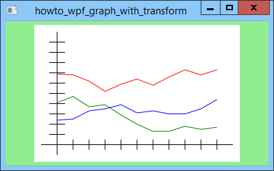
Title: Use transformations to draw a graph in WPF and C#
Background
This example shows how you can use transformations to draw a graph in WPF. In two-dimensional graphics, transformations let you translate, scale, rotate, and skew the objects that you draw. My previous post, Draw a graph in WPF and C#, draws a graph in device coordinates measured in pixels on a Canvas control. This example shows how you can use transformations to let you draw in a world coordinate system that's more convenient for the data. For example, you might like the graph's X coordinates to represent years between 2000 and 2020, and the Y coordinates to represent sales figures between $10,000 and $100,000. WPF provides a Transform class and several sub-classes (ScaleTransform, TranslateTransform, RotateTransform, and SkewTransform) to represent transformations applied to controls. You can set a control's LayoutTransform or RenderTransform property to a transform class to apply the transformation to the control during layout or rendering respectively. For example, that lets you rotate or skew a label relatively easily. If you want to apply multiple transforms to a control, you can combine them in a TransformGroup and then set the LayoutTransform or RenderTransform property to the group. Unfortunately that technique doesn't let you easily convert back and forth between the world and device coordinates. As I mentioned in my previous post, you often need to perform those conversions to draw a graph. Fortunately there's another way you can represent transformations. Instead of using the transform classes, you can use the Matrix class. A Matrix object represents a 3×3 matrix that can store information about translation, scaling, rotation, and skew transformations. A nice feature of matrices is that you can combine them to represent multiple transformations. For example, you can use a single Matrix to represent a translation, followed by a rotation, followed by a scaling, followed by another translation. Another nice feature of matrices is that you can invert them to get a transformation representing the opposite of the original transformation. Finally you can use a Matrix to transform a point from one coordinate system to another.
Preparing the Transformation MatrixThis example creates a Matrix object that converts from world coordinates to device coordinates. It then uses that Matrix to convert data points so they are drawn in their correct positions on the Canvas control. When the program starts, its Window_Loaded event handler starts by executing the following code.
const double wxmin = -10; const double wxmax = 110; const double wymin = -1; const double wymax = 11; const double xstep = 10; const double ystep = 1; const double xtic = 5; const double ytic = 0.5; const double dmargin = 10; double dxmin = dmargin; double dxmax = canGraph.Width - dmargin; double dymin = dmargin; double dymax = canGraph.Height - dmargin; // Prepare the transformation matrices. PrepareTransformations( wxmin, wxmax, wymin, wymax, dxmin, dxmax, dymax, dymin); This code creates some constants to define the world and device coordinate bounds. The world coordinates are wxmin <= x <= wxmax, wymin <= y <= wymax. It uses the margin in device coordinates dmargin to define the device coordinates dxmin <= x <= dxmax, dymin <= y <= dymax. The code also defines increment amounts to use in later for loops (xstep and ystep), and the lengths of tic marks in world coordinates (xtic and ytic). After making those definitions, the code calls the PrepareTransformations method to set up the transformation matrix. Note that I pulled a fast one here by switching the order of the dymin and dymax parameters passed into the method. More on that a bit later. The following code shows the PrepareTransformations method.
// Prepare values for perform transformations. private Matrix WtoDMatrix, DtoWMatrix; private void PrepareTransformations( double wxmin, double wxmax, double wymin, double wymax, double dxmin, double dxmax, double dymin, double dymax) { // Make WtoD. WtoDMatrix = Matrix.Identity; WtoDMatrix.Translate(-wxmin, -wymin); double xscale = (dxmax - dxmin) / (wxmax - wxmin); double yscale = (dymax - dymin) / (wymax - wymin); WtoDMatrix.Scale(xscale, yscale); WtoDMatrix.Translate(dxmin, dymin); // Make DtoW. DtoWMatrix = WtoDMatrix; DtoWMatrix.Invert(); } This code first defines two Matrix objects, WtoDMatrix and DtoWMatrix. They will represent the world-to-device and device-to-world transformations. The PrepareTransformations method first initializes WtoDMatrix to the identity matrix. The identity matrix represents a transformation that leaves a point unchanged. The code then calls the Matrix's Translate method to add a translation transformation to it. In this example, it translates by distance -wxmin in the X direction and -wymin in the Y direction. The result is that it translates the world coordinate area so its corner (xwmin, xymin) has moved to the origin. Next the code gets the amount by which it needs to scale the world coordinates to make them match the device coordinates. For example, to make the world coordinates match the width of the device coordinates, xscale divides by the width of the world coordinate area and multiples by the width of the device coordinate area. After calculating the scale factors, the method calls the Matrix's Scale method to add a scaling transformation to the translation. At this point, the Matrix represents translating to the origin followed by scaling. The code then adds another translation to the Matrix to move the point at the origin to the device coordinate point (dxmin, dymin). The combined transformation Matrix represents moving the world coordinate area to the origin, scaling it, and then moving it into position over the device coordinate area. The method finishes by making an inverse transformation. First it copies WtoDMatrix. It then calls the copy's Invert method. The result is the DtoWMatrix, which represents the inverse transformation from device to world coordinates. (The example doesn't actually use this transformation, but it'll come in handy in a later example.) One extra nice feature about this transformation is that it inverts Y coordinates if desired. Normally controls such as Canvas place (0, 0) in the upper left corner and make coordinates increase down and to the right. In contrast, when you're drawing a graph, you normally want (0, 0) to be in the lower left corner. The program handles this transformation by switching the order of the dymin and dymax coordinates passed into the PrepareTransformations method. That makes the yscale value negative, which flips the Y coordinates upside down to match the device coordinate orientation. It also makes the transformation's final translation move the world coordinate origin (wxmin, wymin) to the lower left corner of the device coordinates as needed.
Using the TransformationSetting up the transformation matrix is a bit of work (it's actually not very long, just a bit confusing), but after the matrix is ready, using it is easy. The following WtoD method applies the matrix to a Point.
// Transform a point from world to device coordinates. private Point WtoD(Point point) { return WtoDMatrix.Transform(point); } This code simply calls the matrix's Transform method, passing it the Point to transform. Getting to this point took some effort, but using the matrix couldn't be any easier. Whenever the program needs to draw something, it first calls the WtoD method to translate the coordinates it's using from world to device coordinates. For example, the following code shows how the program draws the baseline for the X axis. The calls to WtoD are shown in blue.
// Make the X axis. GeometryGroup xaxis_geom = new GeometryGroup(); Point p0 = new Point(wxmin, 0); Point p1 = new Point(wxmax, 0); xaxis_geom.Children.Add(new LineGeometry(WtoD(p0), WtoD(p1))); This code defines two points with world coordinates (wxmin, 0) and (wxmax, 0). It calls WtoD for them, passes the result into the LineGeomtry class's constructor, and adds the resulting object to the X axis's GeometryGroup object. (The previous version of the program did the same thing except it worked in device coordinates so it didn't need to transform the points with WtoD.) The following code shows how the program creates the points for a data set.
PointCollection points = new PointCollection(); for (double x = 0; x <= 100; x += 10) { last_y += rand.Next(-10, 10) / 10.0; if (last_y < 0) last_y = 0; if (last_y > 10) last_y = 10; Point p = new Point(x, last_y); points.Add(WtoD(p)); } That's about all there is to it. Download the example and see the previous post for additional details. Download the example to experiment with it and to see additional details. |