![[C# Helper]](../banner260x75.png)
|
|
 |
![[Beginning Database Design Solutions, Second Edition]](db2_79x100.png)
![[Beginning Software Engineering, Second Edition]](book_sw_eng2_79x100.png)
![[Essential Algorithms, Second Edition]](book_algs2e_79x100.png)
![[The Modern C# Challenge]](book_csharp_challenge_80x100.jpg)
![[WPF 3d, Three-Dimensional Graphics with WPF and C#]](book_wpf3d_80x100.png)
![[The C# Helper Top 100]](book_top100_80x100.png)
![[Interview Puzzles Dissected]](book_interview_puzzles_80x100.png)
![[C# 24-Hour Trainer]](book_csharp24hr_2e_79x100.jpg)
![[C# 5.0 Programmer's Reference]](book_csharp_prog_ref_80x100.png)
![[MCSD Certification Toolkit (Exam 70-483): Programming in C#]](book_c_cert_80x100.jpg)

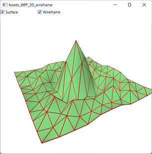
Title: Draw a 3D wireframe using WPF and C#
This example makes it relatively easy to display a 3D wireframe model. It adds three features to previous examples. First, it creates a wireframe representing the triangles defined in a MeshGeometry3D. Second, it modifies earlier segment drawing methods so it can calculate its own "up" vector. Finally, it allows the user to show or hide different parts of the model.
Making the WireframeThe example Draw improved 3D line segments using WPF and C# shows how to draw 3D line segments in WPF. This example uses that technique to draw a wireframe MeshGeometry3D corresponding to a MeshGeometry3D. The following ToWireFrame extension method extends the MeshGeometry3D class and returns a new MeshGeometry3D representing the original mesh's wireframe model.
// Return a MeshGeometry3D representing this mesh's wireframe. public static MeshGeometry3D ToWireframe( this MeshGeometry3D mesh, double thickness) { // Make a dictionary in case triangles share segments // so we don't draw the same segment twice. Dictionary<int, int> already_drawn = new Dictionary<int, int>(); // Make a mesh to hold the wireframe. MeshGeometry3D wireframe = new MeshGeometry3D(); // Loop through the mesh's triangles. for (int triangle = 0; triangle < mesh.TriangleIndices.Count; triangle += 3) { // Get the triangle's corner indices. int index1 = mesh.TriangleIndices[triangle]; int index2 = mesh.TriangleIndices[triangle + 1]; int index3 = mesh.TriangleIndices[triangle + 2]; // Make the triangle's three segments. AddTriangleSegment(mesh, wireframe, already_drawn, index1, index2, thickness); AddTriangleSegment(mesh, wireframe, already_drawn, index2, index3, thickness); AddTriangleSegment(mesh, wireframe, already_drawn, index3, index1, thickness); } return wireframe; } The basic idea is to create line segments to represent each triangle's three edges. However, each edge could be shared by other triangles. To avoid drawing the same edge twice, the ToWireframe method uses a Dictionary<int, int> to hold IDs representing the edges. The AddTriangleSegment method described shortly performs the actual check. The ToWireframe method loops through the original mesh's TriangleIndices collection looking at triples of indices. Each triple holds the indices of the points that make up a triangle. For each triangle, the method calls the following AddTriangleSegment method three times, passing it the indices of the points that make up the triangle's edges.
// Add the triangle's three segments. private static void AddTriangleSegment(MeshGeometry3D mesh, MeshGeometry3D wireframe, Dictionary<int, int> already_drawn, int index1, int index2, double thickness) { // Get a unique ID for a segment connecting the two points. if (index1 > index2) { int temp = index1; index1 = index2; index2 = temp; } int segment_id = index1 * mesh.Positions.Count * index2; // If we've already added this segment for // another triangle, do nothing. if (already_drawn.ContainsKey(segment_id)) return; already_drawn.Add(segment_id, segment_id); // Create the segment. AddSegment(wireframe, mesh.Positions[index1], mesh.Positions[index2], thickness); } The AddTriangleSegment method first determines whether the edge has already been added to the wireframe model. To do that, it calculates the edge's ID. If the original mesh contains NumPoints vertices and the edge's points have indices index1 and index2 where index1 < index2, then the ID is index1 * NumPoints + index2. This scheme guarantees that each edge has a distinct ID in the mesh. If the edge's ID is already in the dictionary, the segment has been added to the wireframe model already so the method exits. If the segment has not yet been added to the model, the method calls the AddSegment method to create it. It then adds the edge's ID to the dictionary so it won't be added again. To create the wireframe, the main program simply calls the surface mesh object's ToWireframe extension method, passing it the thickness the wireframe segments should have. It then creates the wireframe's material and GeometryModel3D, and adds the result to the main model group's Children collection as shown in the following code.
MeshGeometry3D wireframe = mesh.ToWireframe(0.03); DiffuseMaterial wireframe_material = new DiffuseMaterial(Brushes.Red); WireframeModel = new GeometryModel3D(wireframe, wireframe_material); model_group.Children.Add(WireframeModel); Calculating "Up" VectorsAn earlier post explained how to make an AddSegment method that creates a thin box that can represent a line segment in 3D WPF programs. That method required you to include an "up" vector. The AddSegment method made the sides of the thin box parallel to that vector and to the segment's vector. That was convenient for the previous example where the segments were parallel to the X, Y, and Z axes and it was easy to pick perpendicular "up" vectors. Sometimes, however, you don't really care which direction is "up." For this program, I added the following overloaded version of AddSegment that doesn't require an "up" vector.public static void AddSegment(MeshGeometry3D mesh, Point3D point1, Point3D point2, double thickness, bool extend) { // Find an up vector that is not colinear with the segment. // Start with a vector parallel to the Y axis. Vector3D up = new Vector3D(0, 1, 0); // If the segment and up vector point in more or less the // same direction, use an up vector parallel to the X axis. Vector3D segment = point2 - point1; segment.Normalize(); if (Math.Abs(Vector3D.DotProduct(up, segment)) > 0.9) up = new Vector3D(1, 0, 0); // Add the segment. AddSegment(mesh, point1, point2, up, thickness, extend); } The only requirement for the "up" vector is that it can't be parallel to the segment being drawn. This method starts with an "up" vector that is parallel to the Y axis. It then uses the Vector3D class's DotProduct method to calculate the dot product between the normalized segment and the "up" vector. The dot product of two vectors equals the product of the lengths of the vectors and the cosine of the angle between them. In this example, the vectors have length 1, so the result is simply the cosine of the angle. If the cosine is greater than 0.9 (or less than -0.9), then angle between the segment and the "up" vector is small (or offset 180 degrees from a small value). That means the segment and "up" vector point in more or less the same direction (or more or less in opposite directions). In that case, the method uses an "up" vector parallel to the X axis so it doesn't point more or less where the segment does. That ensures that the two are not parallel, as desired. After finding an acceptable "up" vector, the AddSegment method calls the earlier version of itself, passing it the "up" vector.
Showing and Hiding ModelsWhen you click one of the program's check boxes, the program displays the surface, the wireframe, or both. In order to display the models when needed, the program uses the following code to declare variables to hold the surface and wireframe models at the class level.
// The surface's model. private GeometryModel3D SurfaceModel; // The wireframe's model. private GeometryModel3D WireframeModel; When you click a check box, the following event handler executes.
// Show and hide the appropriate GeometryModel3Ds. private void chkContents_Click(object sender, RoutedEventArgs e) { // Remove the GeometryModel3Ds. for (int i = MainModel3Dgroup.Children.Count - 1; i >= 0; i--) { if (MainModel3Dgroup.Children[i] is GeometryModel3D) MainModel3Dgroup.Children.RemoveAt(i); } // Add the selected GeometryModel3Ds. if ((SurfaceModel != null) && ((bool)chkSurface.IsChecked)) MainModel3Dgroup.Children.Add(SurfaceModel); if ((WireframeModel != null) && ((bool)chkWireframe.IsChecked)) MainModel3Dgroup.Children.Add(WireframeModel); } This event handler first loops through the objects in MainModel3Dgroup.Children and removes any that are GeometryModel3D objects. (The other objects in this example are lights.) The event handler then re-adds the selected GeometryModel3D objects to the MainModel3Dgroup.Children collection so they are drawn. Download the example to experiment with it and to see additional details. |
![[WPF 3d]](../book_wpf3d_244x300.png "WPF 3d")