![[C# Helper]](../banner260x75.png)
|
|
 |
![[Beginning Database Design Solutions, Second Edition]](db2_79x100.png)
![[Beginning Software Engineering, Second Edition]](book_sw_eng2_79x100.png)
![[Essential Algorithms, Second Edition]](book_algs2e_79x100.png)
![[The Modern C# Challenge]](book_csharp_challenge_80x100.jpg)
![[WPF 3d, Three-Dimensional Graphics with WPF and C#]](book_wpf3d_80x100.png)
![[The C# Helper Top 100]](book_top100_80x100.png)
![[Interview Puzzles Dissected]](book_interview_puzzles_80x100.png)
![[C# 24-Hour Trainer]](book_csharp24hr_2e_79x100.jpg)
![[C# 5.0 Programmer's Reference]](book_csharp_prog_ref_80x100.png)
![[MCSD Certification Toolkit (Exam 70-483): Programming in C#]](book_c_cert_80x100.jpg)

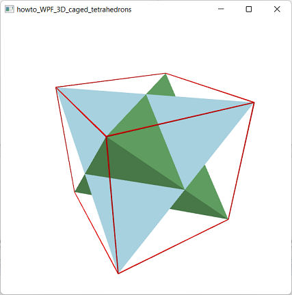
Title: Draw interlocked tetrahedrons in a cage of "line segments" using WPF and C#
This example draws two interlocked tetrahedrons surrounded by a cubic cage of line segments. Unfortunately a noticeable omission from WPF's 3D tools is any way to draw line segments. That means you can't draw wireframe models, show surface normals, or draw other line-like features. You can use the CodePlex toolkit 3D Tools for the Windows Presentation Foundation, but I usually prefer to implement my own solutions if possible. The CodePlex toolkit draws 3D line segments this by drawing skinny rectangles. That works, but if the viewing angle is along the edge of a rectangle, it disappears. Another approach would be to draw two skinny perpendicular rectangles that are interlocked. Then you can see something from any angle (except end-on).
Instead ot taking those approaches, I decided to represent line segments with skinny rectangular prisms (boxes). The following code shows how the AddSegment method adds a prism to represent a line segment connecting two points.
// Make a thin rectangular prism between the two points. private void AddSegment(MeshGeometry3D mesh, Point3D point1, Point3D point2, Vector3D up) { const double thickness = 0.01; // Get the segment's vector. Vector3D v = point2 - point1; // Get the scaled up vector. Vector3D n1 = ScaleVector(up, thickness / 2.0); // Get another scaled perpendicular vector. Vector3D n2 = Vector3D.CrossProduct(v, n1); n2 = ScaleVector(n2, thickness / 2.0); // Make a skinny box. // p1pm means point1 PLUS n1 MINUS n2. Point3D p1pp = point1 + n1 + n2; Point3D p1mp = point1 - n1 + n2; Point3D p1pm = point1 + n1 - n2; Point3D p1mm = point1 - n1 - n2; Point3D p2pp = point2 + n1 + n2; Point3D p2mp = point2 - n1 + n2; Point3D p2pm = point2 + n1 - n2; Point3D p2mm = point2 - n1 - n2; // Sides. AddTriangle(mesh, p1pp, p1mp, p2mp); AddTriangle(mesh, p1pp, p2mp, p2pp); AddTriangle(mesh, p1pp, p2pp, p2pm); AddTriangle(mesh, p1pp, p2pm, p1pm); AddTriangle(mesh, p1pm, p2pm, p2mm); AddTriangle(mesh, p1pm, p2mm, p1mm); AddTriangle(mesh, p1mm, p2mm, p2mp); AddTriangle(mesh, p1mm, p2mp, p1mp); // Ends. AddTriangle(mesh, p1pp, p1pm, p1mm); AddTriangle(mesh, p1pp, p1mm, p1mp); AddTriangle(mesh, p2pp, p2mp, p2mm); AddTriangle(mesh, p2pp, p2mm, p2pm); } The code first gets a Vector3D representing the vector between the start and end points. It then uses the ScaleVector method (which is straightforward) to create a vector n1 in the "up" direction that has length equal to half of the prism's thickness. It uses the Vactor3D class's CrossProduct method to get a new vector n2 perpendicular to the other two. (If you don't know what a vector cross product is, see WikiPedia.) It then scales vector n2 so it also has length equal to half the prism's desired thickness. Next the method adds combinations of the vectors n1 and n2 to the segment's end points to get the corners of the prism. It uses those points to add the necessary triangles to the MeshGeometry3D to build the prism. This approach uses 12 triangles to represent the segment, so it's more work than the CodePlex toolkit's approach, which uses only 2 triangles, but it gives a slightly better result. Still, if you need to draw 100,000 segments, you might want to use CodePlex's approach to save drawing time. Download the example to experiment with it and to see additional details. |