Title: Rotate a 3D cube using XAML and C#

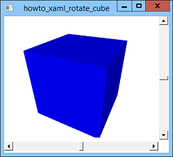
This example shows how to display and rotate a 3D cube using XAML. It displays a blue three-dimensional cube with scroll bars that you can use to rotate the cube to view it from different directions.
The following shows the program's XAML code in its entirety. The XAML code handles all of the user interactions including rotating the cube, so the example doesn't need any C# code behind the scenes.
<Window x:Class="howto_xaml_rotate_cube.Window1"
xmlns="http://schemas.microsoft.com/winfx/2006/xaml/presentation"
xmlns:x="http://schemas.microsoft.com/winfx/2006/xaml"
Title="howto_xaml_rotate_cube" Height="300" Width="330">
<Grid>
<Grid.ColumnDefinitions>
<ColumnDefinition Width="*"/>
<ColumnDefinition Width="20"/>
</Grid.ColumnDefinitions>
<Grid.RowDefinitions>
<RowDefinition Height="*"/>
<RowDefinition Height="25"/>
</Grid.RowDefinitions>
<ScrollBar Name="vscroll"
Grid.Row="0" Grid.Column="1"
Orientation="Vertical"
Minimum="-180" Maximum="180"
LargeChange="10" SmallChange="1" Value="0" />
<ScrollBar Name="hscroll"
Grid.Row="1" Grid.Column="0"
Orientation="Horizontal"
Minimum="-180" Maximum="180"
LargeChange="10" SmallChange="1" Value="0" />
<Viewport3D Margin="4,4,4,4" Grid.Row="0" Grid.Column="0">
<ModelVisual3D>
<ModelVisual3D.Content>
<Model3DGroup>
<!-- Lights -->
<AmbientLight Color="Gray" />
<DirectionalLight Color="Gray" Direction="1,-2,-3" />
<DirectionalLight Color="Gray" Direction="-1,2,3" />
<GeometryModel3D>
<GeometryModel3D.Geometry>
<!-- Cube -->
<MeshGeometry3D
Positions="
-1,-1,-1 1,-1,-1 1,-1, 1 -1,-1, 1
-1,-1, 1 1,-1, 1 1, 1, 1 -1, 1, 1
1,-1, 1 1,-1,-1 1, 1,-1 1, 1, 1
1, 1, 1 1, 1,-1 -1, 1,-1 -1, 1, 1
-1,-1, 1 -1, 1, 1 -1, 1,-1 -1,-1,-1
-1,-1,-1 -1, 1,-1 1, 1,-1 1,-1,-1
"
TriangleIndices="
0 1 2 2 3 0
4 5 6 6 7 4
8 9 10 10 11 8
12 13 14 14 15 12
16 17 18 18 19 16
20 21 22 22 23 20
" />
</GeometryModel3D.Geometry>
<GeometryModel3D.Material>
<DiffuseMaterial Brush="Blue" />
</GeometryModel3D.Material>
</GeometryModel3D>
</Model3DGroup>
</ModelVisual3D.Content>
</ModelVisual3D>
<Viewport3D.Camera>
<PerspectiveCamera
Position = "1.5, 2, 3"
LookDirection = "-1.5, -2, -3"
UpDirection = "0, 1, 0"
FieldOfView = "60">
<PerspectiveCamera.Transform>
<Transform3DGroup>
<RotateTransform3D>
<RotateTransform3D.Rotation>
<AxisAngleRotation3D
Axis="0 1 0"
Angle="{Binding ElementName=hscroll, Path=Value}" />
</RotateTransform3D.Rotation>
</RotateTransform3D>
<RotateTransform3D>
<RotateTransform3D.Rotation>
<AxisAngleRotation3D
Axis="1 0 0"
Angle="{Binding ElementName=vscroll, Path=Value}" />
</RotateTransform3D.Rotation>
</RotateTransform3D>
</Transform3DGroup>
</PerspectiveCamera.Transform>
</PerspectiveCamera>
</Viewport3D.Camera>
</Viewport3D>
</Grid>
</Window>
The window contains a Grid that defines a large row and column and a small row and column. The scroll bars sit in the grid's skinny cells. The large cell in the upper left contains a Viewport3D object that can display a three-dimensional scene. It contains a ModelVisual3D and a Camera.
The ModelVisual3D contains a Model3DGroup that defines some lights to illuminate the scene and a GeometryModel3D. The GeometryModel3D defines the geometry of a three-dimensional object and the material of which it is made.
The GeometryModel3D contains a MeshGeometry3D object to define the cube. That object's Positions values give the positions of the cube's vertices in three-dimensional space. The TriangleIndices property gives the indices of vertices that should be used to make triangles. For example, the first three values in TriangleIndices are 0, 1, and 2, meaning the vertices with indexes 0, 1, and 2 should be used to make a triangle.
Note that the GeometryModel3D can define only one geometry and only one material. That means if you want to make multiple objects with different materials, such as red and blue cubes or a single cube with differently colored sides, then you need to use more than one GeometryModel3D object.
The Viewport3D object's Camera property defines the camera used to view the three-dimensional scene. This example uses a perspective camera positioned at (1.5, 2, 3) looking back at the origin. The UpDirection determines the camera's tilt. In this example, the camera is oriented vertically. The FieldOfView determines how wide an area the camera views.
This example uses two transformations to modify the camera's position. The first is a rotation around the Y axis. The angle of rotation is given by the Value property of the horizontal scroll bar hscroll. The second transformation is a rotation around the X axis through the angle given by the vertical scroll bar's Value property.
Binding the angles of rotation to the scroll bars' Value properties lets the XAML code handle the rotations without requiring any C# code. When you adjust a scroll bar, the rotations' angles update and the cube automatically rotates.
This may seem rather complicated (yes, it is), but it's important to understand how these XAML objects work if you want to build three-dimensional scenes. Download the example and take some time to study it before you move on to more complicated 3D examples. Try some experiments. For example, try adding a second cube with a different color.
Download the example to experiment with it and to see additional details.
|
![[C# Helper]](../banner260x75.png)

![[Beginning Database Design Solutions, Second Edition]](db2_79x100.png)
![[Beginning Database Design Solutions, Second Edition]](db2_79x100.png)