![[C# Helper]](../banner260x75.png)
|
|
 |
![[Beginning Database Design Solutions, Second Edition]](db2_79x100.png)
Title: Understand 3D drawing with WPF, XAML, and C#The previous examples I've posted that use XAML to draw 3D objects are pretty cool, but they're really basically toys. You can sit down and work out the coordinates needed to draw a cube or (with a bit of work) a tetrahedron. However, if you want to draw anything really complicated, such as a 3D surface or a complex world like the one used in World of Warcraft, Guild Wars 2, or League of Legends, you're going to use software to generate the coordinates of the objects you're drawing. You could write a program to calculate those coordinates and use them to generate XAML code, but that would be cumbersome. It would add an extra step and wouldn't let the program change the coordinates at runtime. Obviously the solution is to make the program generate (and possibly modify) the objects at runtime. Before posting examples that generate graphics at runtime, however, I should explain a few issues I've glossed over in previous XAML 3-D posts. Those issues include:
The Coordinate System
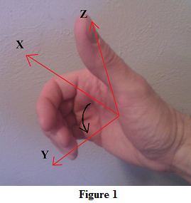
WPF uses a right-handed coordinate system to determine the orientation of the X, Y, and Z axes in relation to each other. It's called a "right-handed" coordinate system because you can use your right hand to verify the axes' relationships. If you extend the fingers of your right hand so they point along the positive X axis and curl them toward the positive Y axis, your thumb points along the positive Z axis. (See Figure 1.) This is called the "right-hand rule." If you extend your fingers along the positive X axis and cannot curl them toward the positive Y axis, you probably need to turn your hand over to make it work. That will flip the direction of your thumb so the Z axis points in the right direction.
In a different version of the right-hand rule, you point your index finger along the X axis and your middle finger along the Y axis. Then your thumb points along the Z axis. (See Figure 2.)
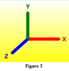
In many 3D programs, the axes are rotated so the X axis points right, the Y axis points up, and the Z axis points toward the viewer as shown in Figure 3. That way if you drop the Z coordinate, you get the usual two-dimensional situation with the X axis pointing right and the Y axis pointing up. You can use either version of the right-hand rule to verify that this is a right-handed coordinate system. Do you need to orient the axes in that way? Not really. As long as you're consistent, use a right-handed coordinate system, and orient the camera and lights in the same way, you can rotate the axes around to suit your intuition. For example, you could make the X axis point right, the Y axis point away from the viewer, and the Z axis point up. You should, however, make sure your axes satisfy the right-hand rule because that rule is used for outward orientation and backface removal described shortly.
Outward Oriented Surfaces and Backface RemovalSuppose you're drawing a scene such as a groups of cubes, and imagine you're looking at the scene from a particular position. The program must draw only the parts of the scene that are visible from your viewing position. If a cube lies behind another cube, you shouldn't draw the first cube. In a harder situation, a be might be partly behind another cube, or it might intersect another cube. In that case the program must draw only the parts of the first cube that should be visible. In general, determining which parts of a scene are visible to a viewing position is pretty difficult, but there is one special case that is easy. For any closed solid, you know that any part of the solid that is on the solid's far side is hidden from view. For example, you can't see the far side of a sphere. Parts of a solid that are on the opposite side from the viewing position are called "backfaces." 3D drawing programs use relatively simple "backface removal" tests to get rid of those faces without drawing them. (A step such as this, which quickly eliminates some faces from consideration, is called "culling.") The relatively simple backface removal test relies on some geometric calculations that depend on the fact that the triangles that make up the solid are "outwardly oriented." That means if you look at a triangle from the outside of the solid (as opposed to looking at it through the solid), the points that make up the triangle should be arranged in counter-clockwise order. If you look at the triangle through the solid, they will be in clockwise order. The orientation of the points as seen from the viewing position lets the program know whether it is looking at the triangle on the front or back of the solid, and that lets it perform backface removal.
Another way of thinking about the orientation is to use the right-hand rule again, this time in a new way. If you curl your fingers so they follow the direction of the points that make up the triangle, your thumb gives the triangle's orientation. To be properly outwardly oriented, your thumb should point away from the solid.
CamerasA camera represents the program's viewing position. To completely specify a camera, you need to give its position and orientation. The position simply specifies the camera's X, Y, and Z coordinates.
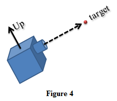
You can specify the orientation in several ways. One of the more intuitive is to give it "look" and "up" directions. The "look" direction determines the direction in which the camera is pointed. The "up" direction determines the camera's "roll" or "tilt." (For example, you could tilt the camera on its side.) Figure 4 shows a camera aimed at a target object. The "up" direction is indicated by a solid arrow. The "look" direction is indicated by a dashed arrow. One more property you should specify for a camera is its field of view. This determines how wide an area the camera can "see." Making the field of view small produces a result similar to a telephoto lens. The camera doesn't see much of what's in front of it and it enlarges that area to fit the display. Making the field of view large produces a result similar to a fish-eye lens. The camera "sees" a lot of what's in front of it and distorts it to make it fit the available viewing area. The following code shows how you might define a camera.
TheCamera = new PerspectiveCamera(); TheCamera.Position = new Point3D(10.0, 20.0, 0.0); TheCamera.LookDirection = new Vector3D(-10.0, -20.0, 0.0); TheCamera.UpDirection = new Vector3D(0.0, 1.0, 0.0); TheCamera.FieldOfView = 30; This code places the camera at (10, 20, 0). It sets LookDirection to the negative of the position values so the camera is looking back toward the origin. The "up" direction is <0, 1, 0> so the top of the camera is directly above the bottom. That's the most usual orientation. Finally the code sets the camera's field of view to 30, which usually produces a good result.
LightsLights are partly responsible for the appearance of objects. For example, if you shine a red light on a white object, the result is red. WPF has several kinds of lights. For now I'll describe the two most useful: ambient lights and directional lights.
Ambient LightsAn ambient light source represents light that is applied equally to everything in the scene. If you look under a desk or chair IRL, ambient light lets you see the floor even if there is no light shining directly on it. In the real world, light reflects off of all of the objects in an area (walls, floor, ceiling, chairs, people, coffee makers, whatever) and provides indirect illumination of everything. The model used by WPF isn't perfectly correct because it applies light equally to everything in the scene. In the real world, objects receive light reflected from nearby objects and that effects their appearance. For example, if you place a white marshmallow next to a bright red apple, the marshmallow will appear slightly pink. If you put the marshmallow next to a black cat, it will receive less reflected light and appear dull gray. In contrast, WPF's ambient light is the same no matter what objects are nearby. If you want a surface to be visible at all times no matter what other light is available, include some ambient light. The following code creates a gray ambient light.
AmbientLight ambient_light = new AmbientLight(Colors.Gray);
Directional LightsThe color of an object depends in part on the angle with which the (non-ambient) light strikes the object's surface. If you shine a white light on a piece of white paper so the light strikes the paper at a 90° angle, the paper appears white. In contrast if you move the light so it strikes the paper at a 30° angle, the paper appears light gray. Because ambient light comes from no particular direction (or every direction, if you prefer), it effects all surfaces equally. In contrast a directional light provides light shining in a single direction so it effects surfaces that are arranged perpendicularly to that direction more than other surfaces. Note that WPF doesn't handle shadows or transparency. That means a light cannot shine through a transparent object and one object cannot block the light and cast a shadow on another object. An object can block its own light, however. For example, suppose you are drawing a cube with top side parallel to the X-Z plane (a horizontal surface), and you have a directional light shining downward. The top of the cube will be brightly lit, but the bottom side is blocked from the light by the object (it's a backface when seen from the position of the light) so it isn't illuminated by that light. Sometimes you may want to use multiple directional light sources to get the best results from a scene, but using more lights slows rendering so don't go crazy. The following code shows how a program might create a directional light.
DirectionalLight directional_light1 = new DirectionalLight(Colors.Gray, new Vector3D(-1.0, -3.0, -2.0)); This code creates a light shining in the direction <-1, -3, -2>.
MaterialsAn object's displayed color depends on the light that shines on it. It also depends on the object's material. If you shine an orange light on a white sphere, the result is orange. If you shine the same light on a bright green sphere, the result is dark green. (The orange has a weak green component, so it doesn't bring out all of the object's bright green color.) WPF has several kinds of materials. Emissive materials generate their own light so they appear brighter than the available light would normally make them. They do not emit light that can illuminate other objects in the scene, however. They just appear brighter than usual. Specular materials are shiny and can have bright spots where the angle of the light bounces off the material towards the camera. For example, a polished apple will have bright highlights but a tennis ball will not. Diffuse materials are the simplest. A diffuse object's color depends on its innate color and the lighting model. The following code shows how a program might use a diffuse material.
// Make the surface's material using a solid green brush. DiffuseMaterial surface_material = new DiffuseMaterial(Brushes.LightGreen); // Make the mesh's model. GeometryModel3D surface_model = new GeometryModel3D(mesh, surface_material); // Make the surface visible from both sides. surface_model.BackMaterial = surface_material; This code first creates a light green diffuse material. It then creates a GeometryModel3D object to represent a set of triangles. It associates the model with the material and a mesh that was previously filled with point and triangle vertex data. Finally this example sets the model's BackMaterial to the same material so the triangles are visible from both sides.
ConclusionThose are the basics of 3D drawing with WPF and XAML in C#. Here are the key points to take from all this:
Now that you know a bit about these issues, you may want to go back and review some of my earlier 3D WPF examples. In their descriptions I didn't talk about the coordinate system, camera, lights, or materials, but if you look at the XAML code you should be able to figure them out. With this background you're also ready to move on to more advanced examples. My next few posts show how programs can generate and display models at runtime. I'm sure I'll have more examples at some point that demonstrate different materials and lighting models, but for now feel free to modify the examples to experiment with them on your own. |
![[Beginning Software Engineering, Second Edition]](book_sw_eng2_79x100.png)
![[Essential Algorithms, Second Edition]](book_algs2e_79x100.png)
![[The Modern C# Challenge]](book_csharp_challenge_80x100.jpg)
![[WPF 3d, Three-Dimensional Graphics with WPF and C#]](book_wpf3d_80x100.png)
![[The C# Helper Top 100]](book_top100_80x100.png)
![[Interview Puzzles Dissected]](book_interview_puzzles_80x100.png)
![[C# 24-Hour Trainer]](book_csharp24hr_2e_79x100.jpg)
![[C# 5.0 Programmer's Reference]](book_csharp_prog_ref_80x100.png)
![[MCSD Certification Toolkit (Exam 70-483): Programming in C#]](book_c_cert_80x100.jpg)


